
User Manual
Tri-band GSM and 3G and DCS RF Repeater
(890-915/935-960MHz, 1710-1785/1805-1880 MHz, 1920-1980/2110-2170MHz, 37dBm)
Table of Contents:
1. Technical Features
2. Specifications
3. Principles
4. Control unit
5. Installation

Technical features
Cavity filter gives better gain flatness, higher stability and low noise figure;
Allowing continuous gain adjustment and contrast gain;
ALC technology used to provide auto amplitude fixation.
Power, uplink and downlink output indications.
Die-casting cabinet can be used indoor and outdoor.
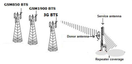
Typical use for RF repeater
2. Specifications
Main subject |
Specification (at consumer's requirement) |
||
Uplink |
Downlink |
||
Frequency Range |
GSM900 |
890-915MHz |
935-960MHz |
DCS1800 |
1710-1785MHz |
1805-1880MHz |
|
3G |
1920-1980MHz |
2110-2170MHz |
|
Maximum gain |
95dB |
95dB |
|
ALC |
20dB |
||
Frequency error |
≤ ±0. 5 ppm |
||
Gain Control Range |
31dB |
||
Step gain |
1dB |
||
RF output power |
GSM900 |
33dBm |
37dBm |
DCS1800 |
33dBm |
37dBm |
|
3G |
33dBm |
37dBm |
|
Noise figure |
≤ 5dB |
||
Group delay |
≤ 1.5US |
||
Band flatness |
≤ 3dB |
||
Intermodulation attenuation |
GSM900 |
≤ -40dBc / 30KHz |
|
DCS1800 |
≤ -40dBc / 30KHz |
||
3G |
≤ -50dBc / 30KHz |
||
Outband (0ff 2.5 MHz) |
≤ -36dBm/30KHz@9KHz-1GHz |
||
≤ -30dBm/30KHz@1GHz-12.75GHz |
|||
Outband rejection |
≤ -30dBc/30KHz@±200KHz |
||
≤ -60dBc/30KHz@±400KHz |
|||
Spurious emission |
≤ -36dBm/30KHz@9KHz-1GHz |
||
≤ -30dBm/30KHz@1GHz-12.75GHz |
|||
VSWR |
≤ 1.5 |
||
Port Number |
1 donor, 1Service Port |
||
Dimensions (mm) |
580mm x355mm x250mm |
||
Weight (Kg) |
25kg |
||
Power supply |
220, 110VAC |
||
Working temperature |
. -25 ℃ ~ + 55 ℃ |
||
Working humidity |
≤ 95% |
||
Enclosure protection |
IP65 |
||
RF connector |
N-F |
||
Operating configuration |
Key-press |
LCD display, manual key-press, |
|
Local PC |
PC RS232 port, |
||
Remote PC |
GSM modem port |
||
3. Principles
3.1 repeater scheme
The repeater consists of diplexer, LNA, filter, PA, MCU, power module. Please refer to the block diagram below for details:

3.2 Working principle
Upon being received by the repeater, the signals from the base station downlink will go through the duplex printing unit, which acts to filter the spurious out-send and then further through the downlink LNA, filter and power amplifier, reaches the repeater end, where the signals are passed through the antenna duplexer and broadcast to the entire area covered, thus completing a round of downlink channel function. When the service antenna receives the transmit signals from a subscriber, the signals will undergo LNA treatment, filter and power amplifier first and then transmitted to the base station, thus achieving the connection between subscribers in blind signal area and the base station. In this way, blind areas are eliminated. Considering receiving coverage size and signal strength may vary with the sites where the repeater is located, it is necessary to control the gain and output of the repeater in addition, considering the fading effect on spatial signal transmission, the amplitude of the auto-fixing is required for the output. For this purpose, MGC and ALC circuits are included in the downlink channels.
4. Control unit


4.1 Real Downlink gain = maximum downlink gain - real downlink ATT value
4.2 Real Uplink gain = maximum Uplink gain - actual value Uplink ATT
4.3 Actual Downlink output power = actual Downlink gain + actual received signal level with oil dispensing antenna
5. Installation
5.1: draft survey
5.1.1 received alone
The donor antenna can receive signal better than - 60dBm. If the signal is not good then the repeater will not work and easy to be exciting.
5.1.2 isolation
The vertical distance from donor antenna to service antenna should be at least 15 meters, or horizontal direction from donor antenna to service antenna should be at least 35 meters. Meanwhile the donor antenna and service antenna should be opposite, pointing in opposite direction.
5.1.3 service antenna height
It will mainly determine the boundary of the coverage area. At least 20 meters height of service antenna is to recommend. It depends on embodying the condition of the coverage area.
5.1.4 Map drawing
For further visual examination, the viewpoint drawing and sectional drawing is necessary. The drawing requirements are as follows:
5.1.4.1 Contour line is classified by 20m to view map.
5.1.4.2 Shadow place as the coverage area, the terrain there if it is very clear with thin trees, only brick and civil engineering structures.
5.1.4.3 Sectional drawing pls check as next of this overlook drawing in green line.
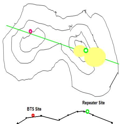
Figure 1: Overlook drawing
5.2: project implementation
5.2.1 Donor antenna installation
5.2.1.1 Tools for location

5.2.1.2 The requirement for received signal
Received BCCH first level: plus - 60dBm
Received BCCH second level: minus 10dB from first BCCH
5.2.1.3 Holding the Yagi antenna for space location, you should address Yagi antenna donor BTS. Read and write the RX level value, Eq/Io value and PN number ready for all PN.
5.2.1.4 Check the data to see if the clause of "5.2.1.2" above known if the clause "5.2.1.2" is not fulfilled, adjust the space location and address of the Yagi, until the clause "5.2.1.2" are met
5.2.1.5 You should install the donor antenna according to the Yagi space and direction location.
5.2.1.6 To connect the donor antenna fixed terminal with RF cable and make adjustment of the donor's space location and direction, until you get best value for received level and CE/IO. Finally, you must be sure that clause "b") are met
5.2.2 Service antenna installation
5.2.2.1 Isolation : the vertical distance from donor antenna to service antenna should be at least 15 meters, or the horizontal direction from donor antenna to service antenna should be at least 35 meters. Meanwhile the donor antenna and service antenna should be opposite, pointing in opposite direction.
5.2.2.2.2 Service antenna height will mainly determine coverage area boundary. More than 20 meters height of service antenna is to recommend. It depends on the embodiment of the coverage area condition.
5.2.3 Repeater installation

5.2.4 Repeater adjustment
Firstly, you should adjust the gain of UL and DL to the smallest, in other words, the attenuation should be maximum 30dB.
Secondly, you should increase DL gain 1dB by 1dB, until the expected output power. If self-excitation occurs, you will need to adjust DL gain 5dB lower to less than its current value.
Thirdly, to set the UL gain 5-10dB lower than DL gain.
5.2.5 Calling a test on the repeater coverage
5.2.4 Setting repeater
Firstly, you should set the UL gain and DL gain to the smallest, in other words, the attenuation should be the maximum 30dB.
Secondly, you should increase DL gain 1dB by 1dB, until the expected output power. If self-excitation occurs, you will need to adjust DL gain 5dB lower to less than its current value.
Thirdly, to set the UL gain 5-10dB lower than DL gain.
5.2.5 Calling test on repeater coverage